
12T × 600 mm electric servo press brake
Compact, oil-free bending for small precision components.
View electric servo press brakePrecision bending. Carter support.
Graphical CNC control, powered backgauge positioning and automatic mechanical crowning. Supplied with tooling, Fiessler laser guarding, commissioning and basic training.
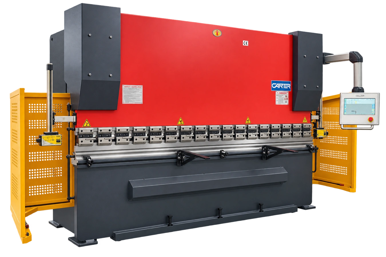 Carter 5-axis CNC · representative machine
Your machine. Your specification.
Choose a model to view its full specification and download a quotation.
A 3,400 mm working length and 125-ton capacity, with 3,000 mm between the side frames. Supplied with Carter 5-axis CNC control and the standard equipment below.
| Model | Carter 3400 × 125T |
|---|---|
| Nominal force | 1,250 kN |
| Working length | 3,400 mm |
| Distance between frames | 3,000 mm |
| Throat depth | 320 mm |
| Backgauge travel | 600 mm |
| Ram stroke | 140 mm |
| Ram stroke adjustment | 50 mm |
|---|---|
| Strokes per minute | ≥8 / min |
| Maximum open height | 405 mm |
| Main motor | 7.5 kW |
| Machine weight | 8.5 t (8,500 kg) |
| Overall dimensions · L × W × H | 4,100 × 1,800 × 2,580 mm |
| Inside-face frame clearance | Available on request |
Use the selected model’s dimensions and weight in the specification above. Ask us for any measurements shown as available on request.
Allow room for the material, operator, maintenance and safe access. Machine dimensions alone do not describe the full working space.
415V three-phase supply unless the selected model states otherwise.
Send your doorway width and height, delivery postcode and a photograph of the planned machine position.
Tell us what unloading equipment you have. We will confirm delivery, offloading, positioning and any commissioning or training in your quotation.
Discuss workshop fitWhat each control does
Control the bend depth, gauge position, pressure and mechanical crowning.
Sets the ram depth for the required bend angle.
Moves the backgauge forwards and backwards to set the flange length.
Raises and lowers the backgauge for different bend stages.
Automatically calculates and controls bending force.
The Anti-Deflection System compensates for deflection through mechanical lower-beam crowning.
A closer look
A closer look at the equipment supplied with your machine.
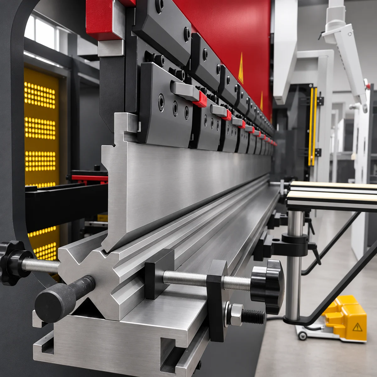
Adjustable top tool holders with safety tang for straightforward tool changes.
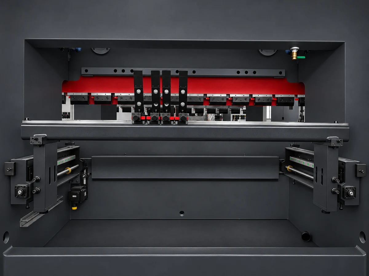
Two probes on linear guides, with manual finger spacing across the machine.
Laser safety equipment mounted beside the tooling.
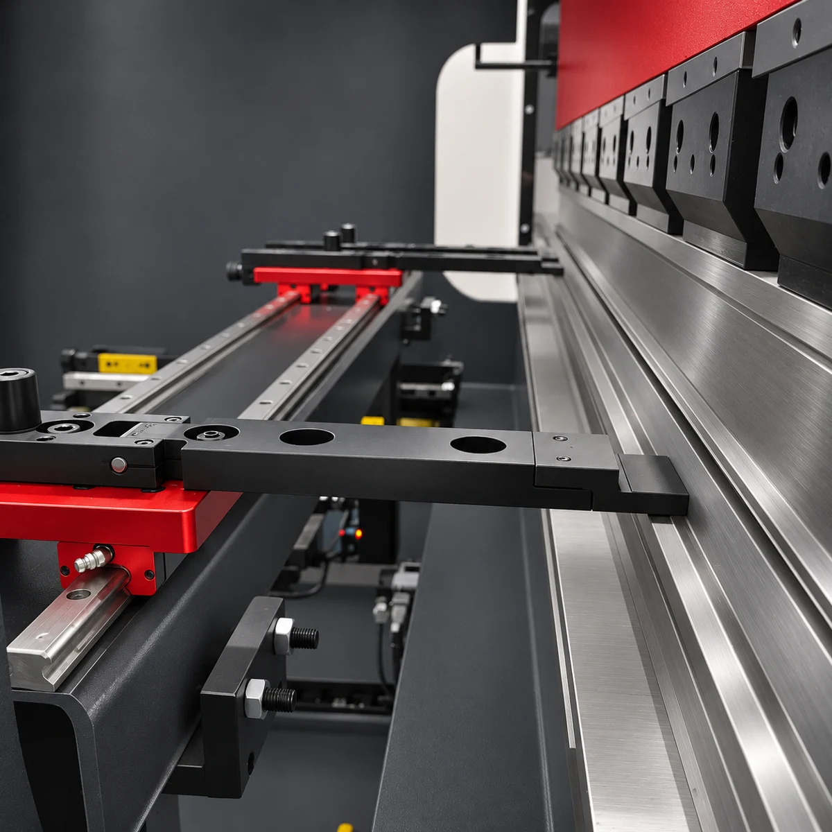
Backgauge drive and guide arrangement for controlled positioning.
The electrical control and servo-drive equipment fitted to the machine.
Included with your machine
Machine price, full available specification, standard equipment and payment terms.
30% deposit with order. Balance before delivery/collection. Terms and conditions apply.
Prices exclude VAT and delivery. Commissioning and basic training included.
Workshop video
A 58-second guide to tooling, clearance, bend sequence, hole spacing and first-part inspection.
Watch with sound or follow the on-screen captions. Video in English.
Read the bending guideWatch the controller, bending beam and backstop together as the machine runs the same six-step programme.
Separate dry-run recordings synchronised by programme step, without sheet material. Watch for the highlighted 250 mm automatic backgauge retraction. Use full screen for a closer view.
The graphical controller advances through six programmed steps. The front view shows the upper beam lowering and returning. The rear view shows the backstop changing position between steps. All three views show the same programme on the Carter 5-axis press brake, including 250 mm automatic backgauge retraction for clearance.
The video could not load. Open the demonstration directly or try again.
Watch Alex enter a profile and work through the bend settings on this machine’s controller. The graphical shape and programme table show how the job is set up.
Original demonstration on the 3400 × 125-ton press brake. Use full screen to read the settings.
Carter Bend Studio
Follow a bend sequence, see the axis movements and explore tools for your component.
See the 3400 × 125-ton press brake from the front, sides and rear. Select a photograph or swipe through the available views, then zoom in for a closer look.
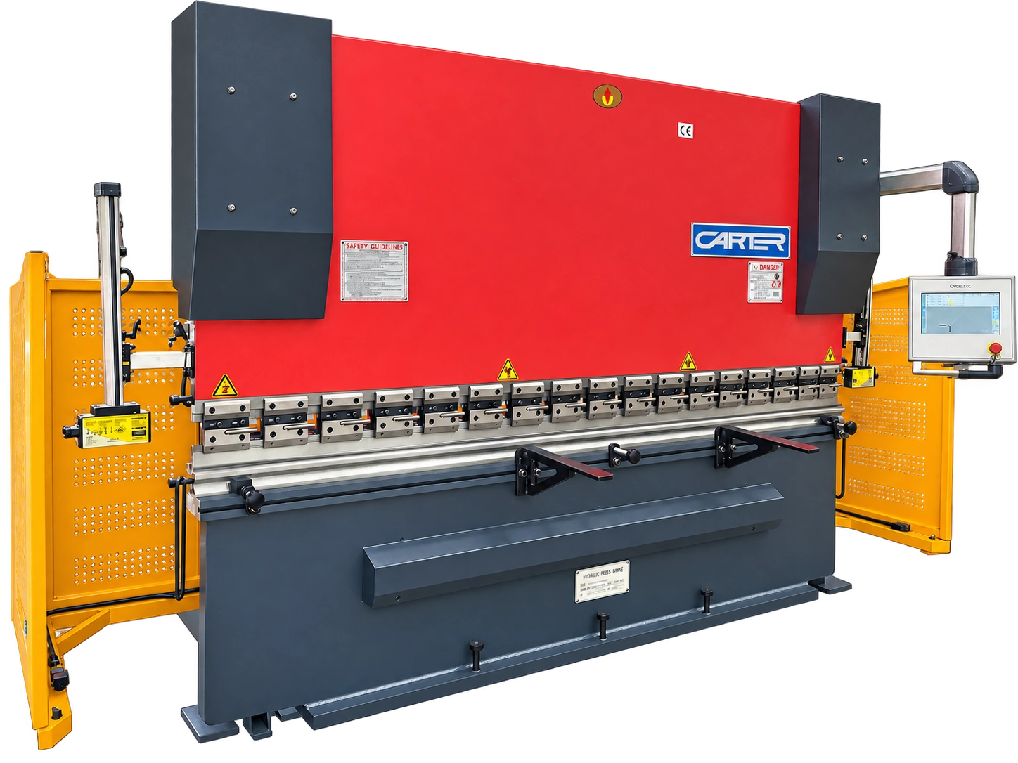 Front · 1 of 6
Six views of the actual machine. Swipe, drag or use the arrow keys to browse.
Crowning, electrical and guarding equipment on the 3400 × 125-ton press brake. Select an image to inspect the detail at full size.
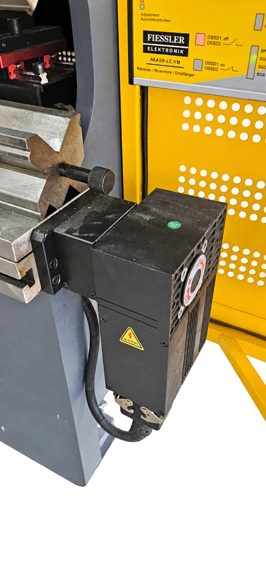
The drive and gearbox at the end of the lower bed. The controller’s crowning setting adjusts the mechanical compensation system.
How crowning works
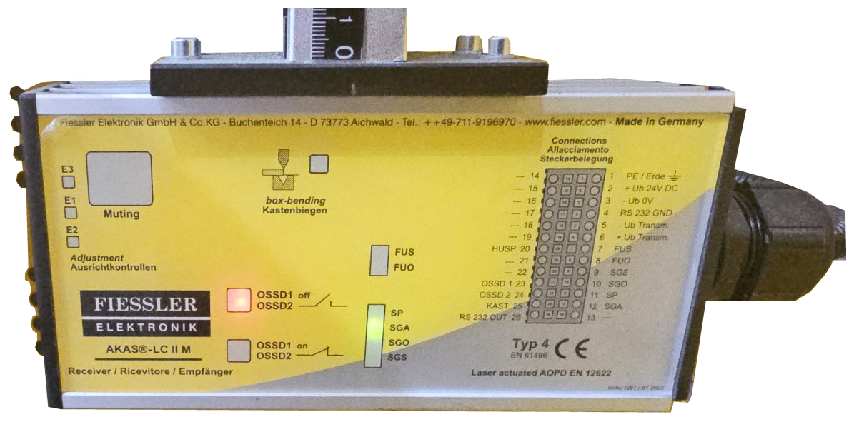
The transmitter and receiver fitted beside the tooling, shown with their original labels and indicators.
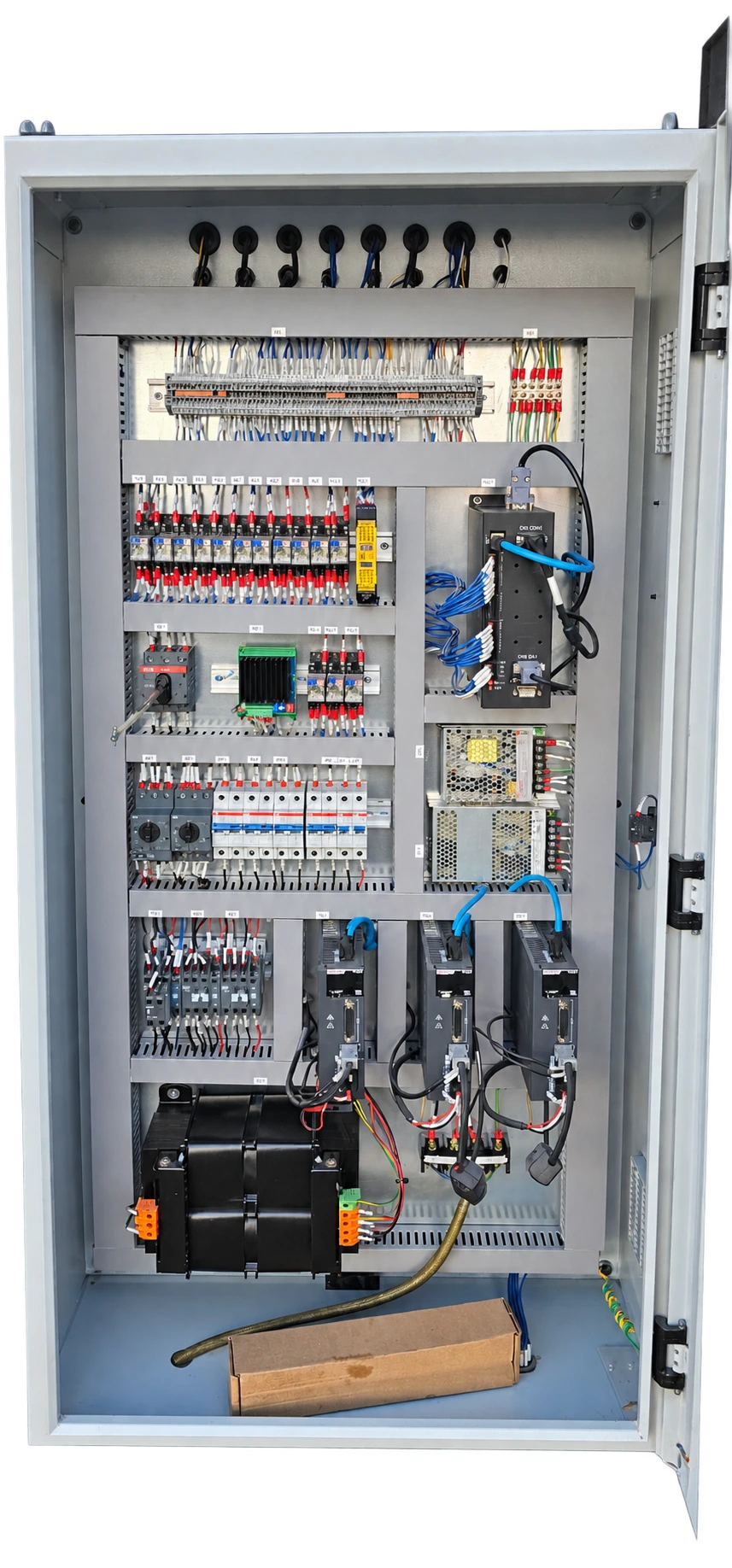
A clear view of the control equipment, labelled wiring terminals and drive units fitted to this machine.
Browse the Euram punches and dies catalogue or use the bending guide to estimate force and preview a bend setup.
Call for sales, spares, service or a quotation.
Lifetime technical support
Lifetime technical support for machinery supplied by Carter. Telephone and email advice continues after the warranty ends.
All new machines include a 24-month parts-and-labour warranty. Ask about part exchange, finance, delivery, offloading and positioning when requesting your quotation.
Finance is subject to approval. Delivery, handling and positioning are quoted for your machine and site.
Sharper corners. Smaller bend radii.
CARTER WORKSHOP GUIDE
See how inside radius, K-factor and bend deduction affect the finished part.
These silent animations use a worked example, not a universal deduction table. Different angles, radii, materials, tooling and hems require their own validated allowances. Confirm the dimension convention on the drawing and prove the flat length on a test piece.
A series of closely spaced, shallow bends approximates a larger radius. Also called step bending or facet bending, this process can produce curved panels, covers and transitions.
Small facets and tool marks may remain. Closer spacing can improve the approximation, but tooling and sheet support limit the usable pitch.
Suitable standard punches and dies can often be used. Tight radii, short steps or restricted access may need a different tool arrangement.
This depends on the radius, total change in direction and acceptable faceting. More strokes increase cycle time; there is no universal bend count.
Springback, material variation, tool alignment, stroke depth and feed spacing all influence the result. Axis repeatability is not a guarantee of finished-radius accuracy.
Suitability depends on the selected model, controller functions, tooling, capacity and part clearance. Ask Carter to check your drawing; automatic radius programming is not assumed.
Rolls may suit long continuous curves and cylindrical work. Bump bending can suit parts that also need straight folds; compare finish, geometry and production volume.
Find hydraulic filters, oils, cutting fluid, linisher belts, laser supplies and machine-specific replacement parts.
Use the manual for the exact model and fitted equipment. These guides support training and job planning; they do not authorise a setup or replace a site-specific risk assessment.
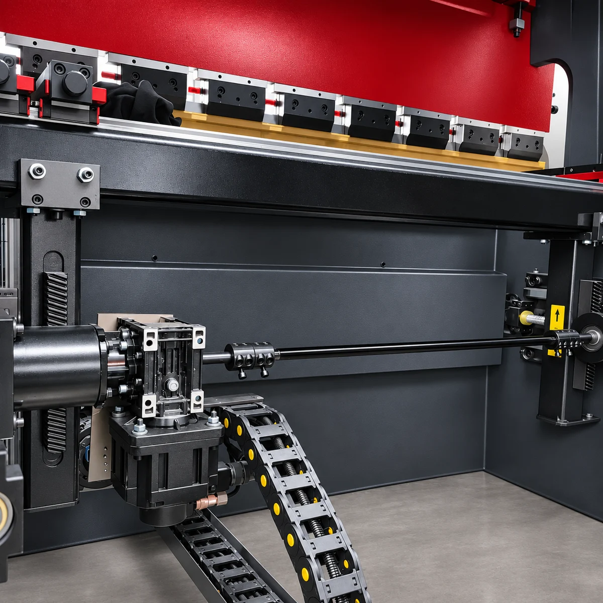
Behind the build
See the frames and beams for CARTER press brakes during production, from heavy steel structures to machining of the working faces.
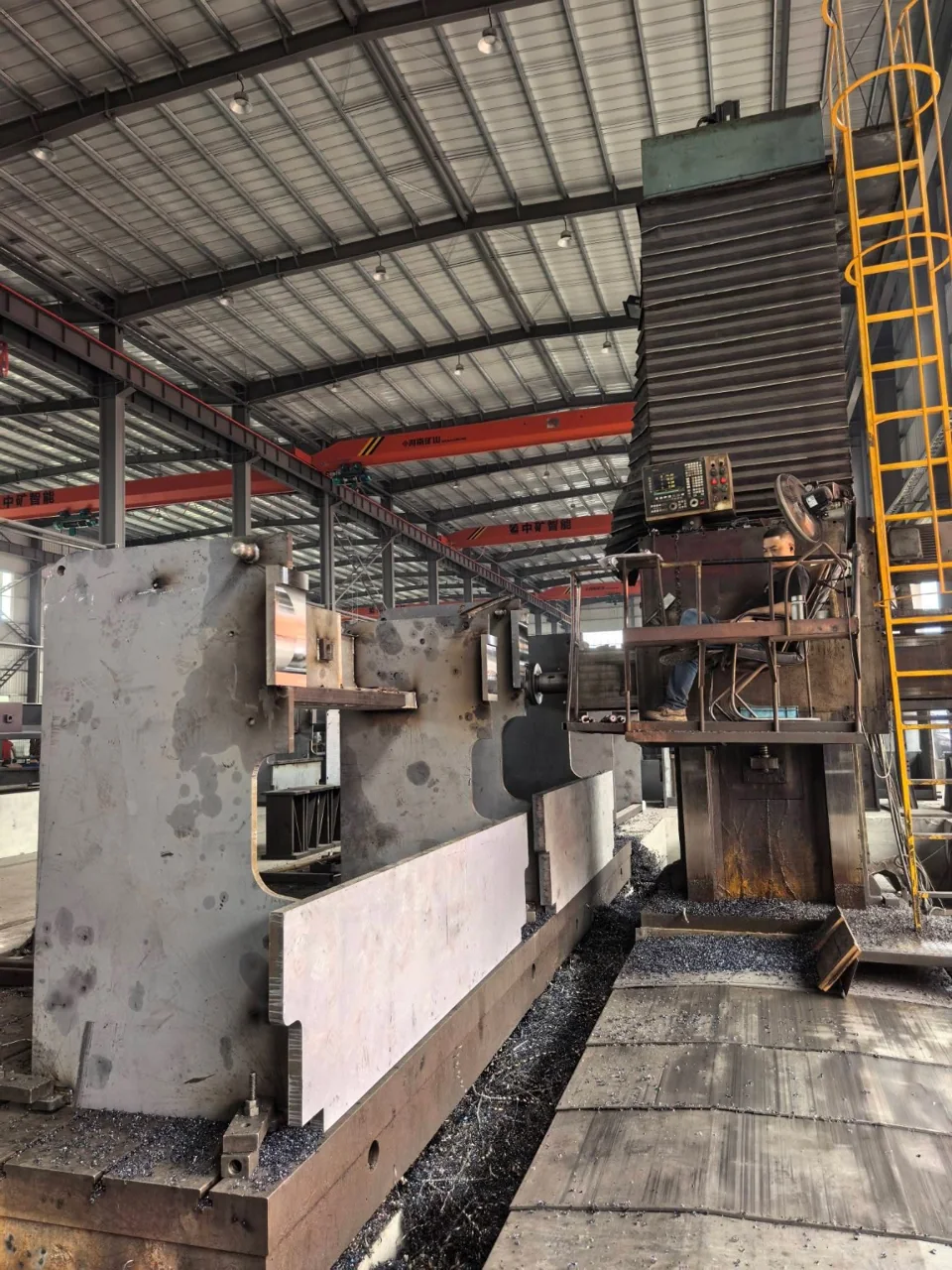
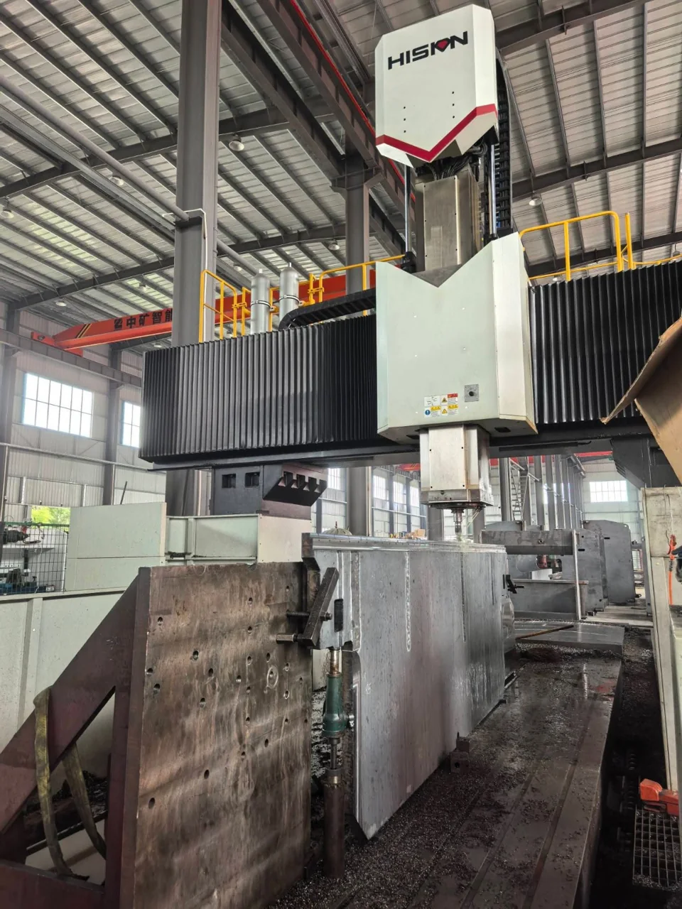
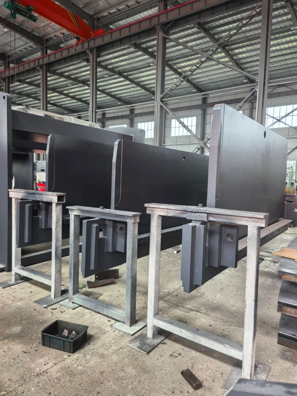
Production photographs from the CARTER press brake range. Frame design and construction vary by model.
Discuss your press brake requirements