1. Position and clamp
Support the sheet, set the groove positions and clamp it securely.
Sharper corners. Smaller bend radii.
Cut a controlled V-shaped groove into sheet metal before folding on a press brake.
A V-groover removes a narrow strip of material along a planned bend line. The sheet is then folded on a press brake, with the groove on the inside of the bend.
Reducing the thickness at the fold allows a smaller corner radius and requires less bending force. It is particularly useful where the appearance of a crisp edge matters.
Support the sheet, set the groove positions and clamp it securely.
Program the depth and position. Cutting tools remove material in controlled passes, leaving a continuous thickness beneath the groove.
Move the prepared sheet to the press brake, form the bend and inspect the corner and surface finish.
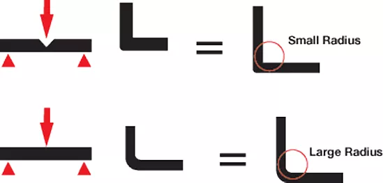
The upper example shows the groove prepared before folding. The lower example shows the larger rounded corner of a conventional bend.

The diagram shows compression on the inside, stretching on the outside and local concavity at the radius. On visible architectural work, that change can affect the reflected finish.
Diagrams supplied for this page from The Fabricator. Click either image to view it at its original size. Labels within the drawings remain in English.
Suitable materials include stainless steel, mild steel, aluminium and copper, subject to the selected machine, cutters and material condition.
Typical uses include lift interiors, decorative wall panels, door surrounds, cabinets, display fittings and architectural metalwork.
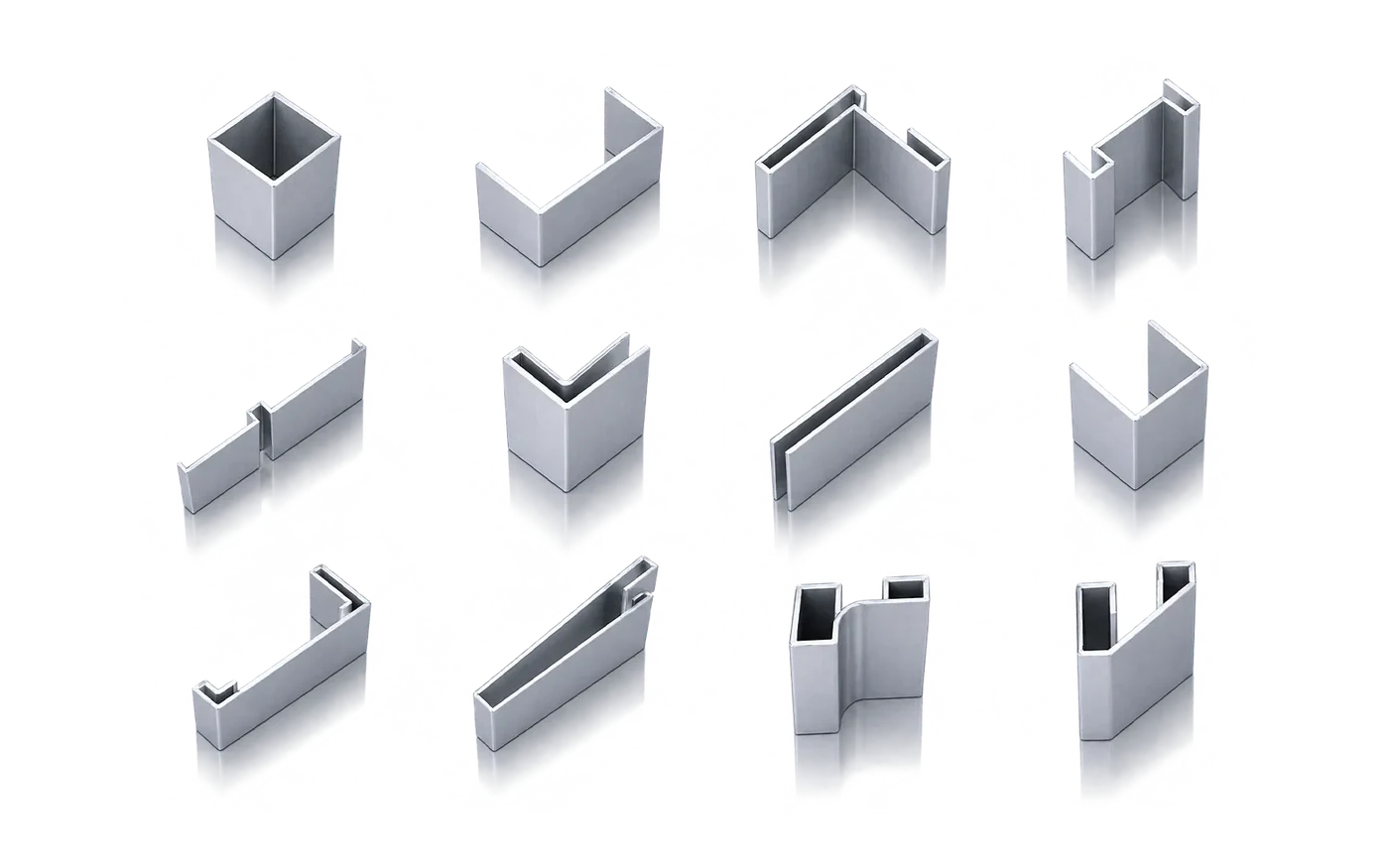
Illustrative examples include channels, corner trims, box sections and folded returns. The complete section must be checked for groove access, bend order and press-brake clearance.
CNC positioning and depth control, secure sheet clamping, rigid tool holders, cutting inserts and panel supports help maintain consistent groove placement and depth.
Confirm the clamping system, number of cutting tools, controller and sheet supports for the chosen configuration.
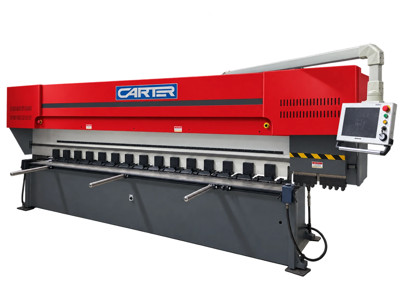
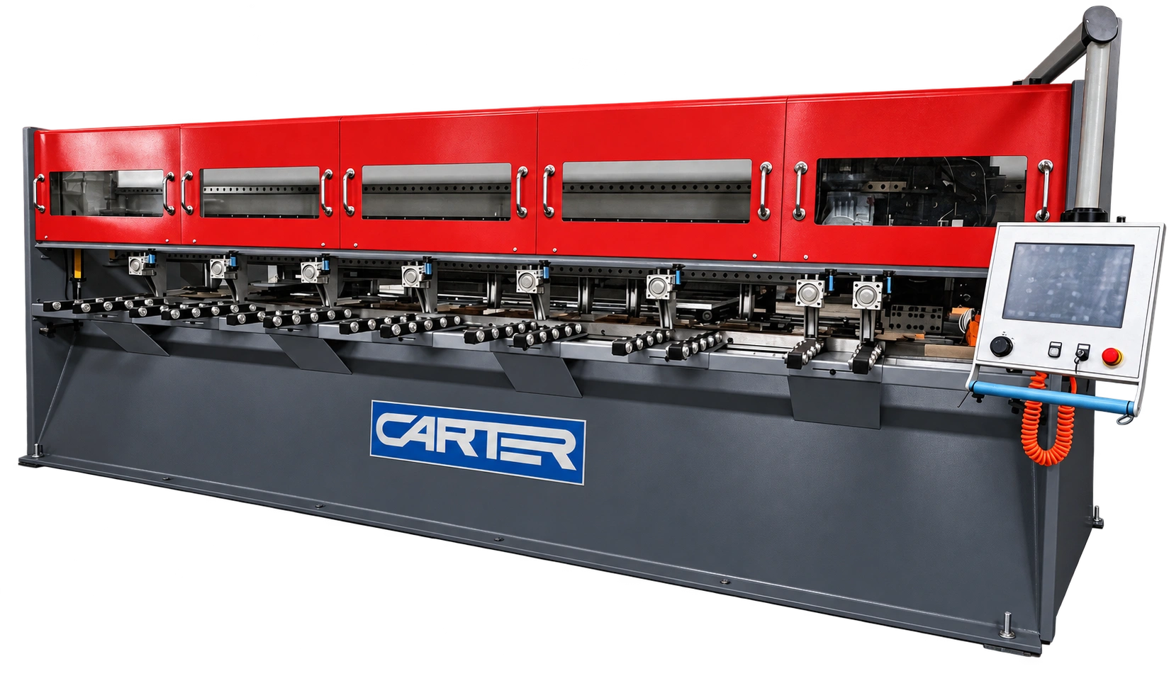
A further machine example from the supplied photographs. Control, clamping and guarding arrangements vary by model; the quotation defines the equipment supplied.
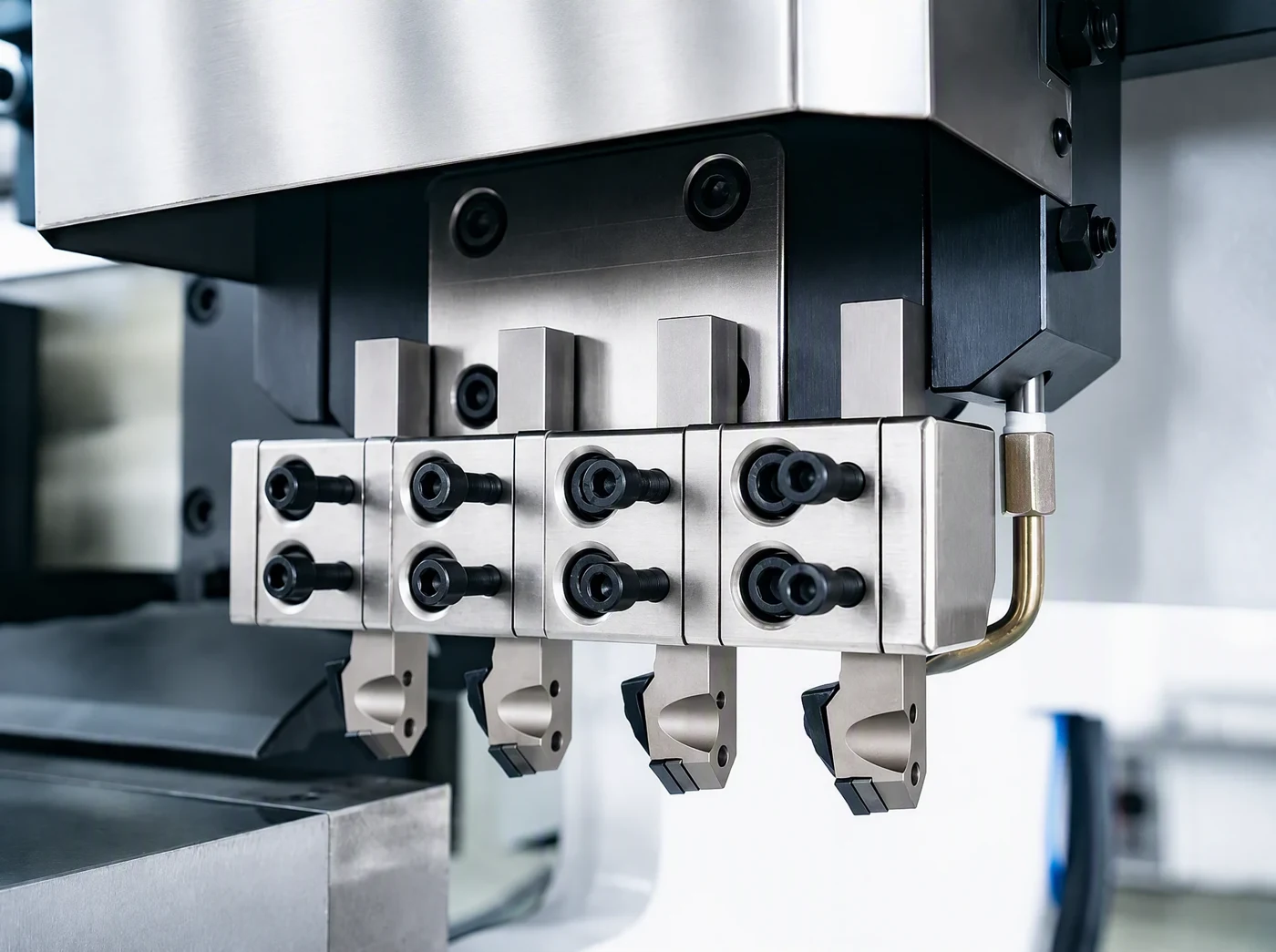
This example shows a sequence of cutting tools. A planned series of cuts forms the groove; tool condition and pass depth affect the finish and remaining metal.
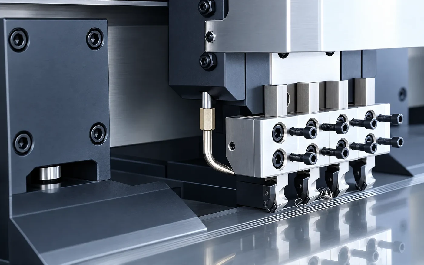
Sheet support and secure clamping maintain the reference during machining. The cutting head removes metal along the programmed groove line.
Process reference images illustrate the method, rather than a guaranteed standard configuration.
Groove depth, included angle and remaining thickness must match the material and required bend. Trial the complete grooving and folding process on a representative sample.
V-grooving removes metal and reduces strength at the fold. It does not replace the press brake, and published sheet thickness is not the depth of a single cutting pass.
The tables describe two separate reference ranges. They are not a combined specification or confirmation of the machine pictured. Final capacity and equipment are confirmed in the Carter quotation.
| Processing length × width (mm) | Sheet thickness (mm) | Weight (kg) | Overall length × width × height (mm) |
|---|---|---|---|
| 2000 × 1250 | 0.4–8 | 5000 | 3400 × 2600 × 2100 |
| 2500 × 1250 | 0.4–8 | 6000 | 4100 × 2600 × 2100 |
| 2000 × 1500 | 0.4–8 | 5000 | 3400 × 2600 × 2100 |
| 3200 × 1500 | 0.4–8 | 8000 | 4800 × 2600 × 2100 |
| 4000 × 1500 | 0.4–8 | 9000 | 5600 × 2600 × 2100 |
| 5000 × 1500 | 0.4–8 | 12000 | 6600 × 2600 × 2100 |
| 6000 × 1500 | 0.4–8 | 14000 | 7600 × 2600 × 2100 |
| 8000 × 1500 | 0.4–8 | 18000 | 9600 × 2600 × 2100 |
| 6000 × 2000 | 0.4–8 | 15000 | To confirm |
Published positioning accuracy: ±0.01 mm on X, Y, Z1 and Z2 axes. Published axis speeds: X and Y up to 90 m/min; Z1 and Z2 up to 30 m/min.
| Processing length × width (mm) | Sheet thickness (mm) | Overall length × width × height (mm) |
|---|---|---|
| 3200 × 1250 | 0.4–6 | 5000 × 2550 × 2100 |
| 3200 × 1500 | 0.4–6 | 5000 × 2800 × 2100 |
| 4000 × 1250 | 0.4–6 | 5800 × 2550 × 2100 |
| 4000 × 1500 | 0.4–6 | 5850 × 2800 × 2100 |
Published cutting speed: 0–90 m/min; return speed: 0–120 m/min. Main servo motor: 4.4 kW. Minimum edge distance: 8 mm.
Maximum thickness depends on material, flatness and groove geometry. Axis speed is not the finished-part production rate.
Tell us your material, sheet size, thickness and required bend finish. Machine capacity, equipment and price are confirmed with your quotation.
Conventional bending stretches the outside face and compresses the inside face. On decorative panels, local distortion can affect how light reflects along the bend. Removing material at the fold can reduce this effect and produce a sharper-looking edge.
The remaining web is the metal left between the groove root and the visible face. Its thickness affects corner radius, springback and strength. A deeper groove is not automatically better: use a trial piece to establish a suitable balance for the actual material and finish.
Check material grade and condition, groove consistency, sharpness of the cutters and press-brake alignment. Use controlled passes and inspect the folded sample before committing to a production run.
For brass and other copper alloys, bendability depends on alloy, temper and bend direction relative to rolling. A grade that machines readily is not automatically the best choice for a sharp fold. Confirm the sheet specification and prove the grooved bend on a sample.
Grooving cannot guarantee a crack-free result. A rough groove, unsuitable remaining thickness or a material that cannot tolerate the required strain can still produce defects.
The groover prepares the bend line by removing metal. The prepared sheet is subsequently formed, normally on a press brake. It is a separate operation in the production route.
A grooved bend has different geometry from a full-thickness bend. Develop and validate the flat pattern for the actual groove and remaining web; do not assume an unmodified bend deduction will give the correct blank.
No. Remaining thickness, groove geometry and material behaviour must be considered together. Use the required appearance and strength, followed by a sample trial, to establish the process.
Removing metal reduces the section at the bend. Where strength, fatigue or impact matters, the joint requires a suitable design assessment rather than judging it by appearance.
Include material grade, thickness, finish, sheet size, section dimensions and production quantity. A drawing and sample requirement help define the machine and the finished-bend acceptance criteria.
Request a Quote