2-axis NC
Straightforward bending with a lower initial investment. A practical choice when you are happy to make more settings manually.
Powered Y and X. Manual pressure control and manual Z positioning.
View 2-axis NC press brakesPrecision bending. Carter support.
Press brakes bend sheet metal into precise angles. Independent backgauge positioning. Programmable ram, pressure and crowning control.
Your machine. Your specification.
Choose a model to view its full specification and download a quotation.
Independent backgauge positioning. Programmable ram, pressure and crowning control.
| Rated bending capacity | 125 tons |
|---|---|
| Nominal pressure (kN) | 1250 |
| Working table length (mm) | 3400 |
| Frame clearance (mm) | 3000 |
| Throat depth (mm) | 320 |
| Backgauge travel (mm) | 600 |
| Ram stroke (mm) | 200 |
|---|---|
| Strokes per minute | at least 8 |
| Maximum open height (mm) | 450 |
| Main motor power (kW) | 7.5 |
| Machine weight (tons) | 8.5 |
| Overall L x W x H (mm) | 3750 x 1550 x 2510 |
Column centre-line spacing and clear frame opening are different measurements.
All prices below are + VAT and delivery. Ask us to confirm availability and the specification for your chosen size. Larger sizes available on request.
Use the selected model’s dimensions and weight in the specification above. Ask us for any measurements shown as available on request.
Allow room for the material, operator, maintenance and safe access. Machine dimensions alone do not describe the full working space.
415V three-phase supply unless the selected model states otherwise.
Send your doorway width and height, delivery postcode and a photograph of the planned machine position.
Tell us what unloading equipment you have. We will confirm delivery, offloading, positioning and any commissioning or training in your quotation.
Discuss workshop fitChoose a large-capacity machine. All models in this range are POA (price on application).
POA — Price on application
Request a quotation| Rated bending capacity | 300 tons |
|---|---|
| Nominal pressure (kN) | 3000 |
| Working table length (mm) | 3200 |
| Working table width (mm) | 300 |
| Distance between columns (mm) | 2680 |
| Throat depth (mm) | 400 |
| Ram stroke (mm) | 250 |
| Maximum open height (mm) | 520 |
| Ram approach speed (mm/s) | 100 |
| Ram working speed (mm/s) | 8 |
| Ram return speed (mm/s) | 100 |
| Main motor power (kW) | 22 |
| Overall L x W x H (mm) | 3500 × 2260 × 3400 |
| Machine weight (kg) | 20000 |
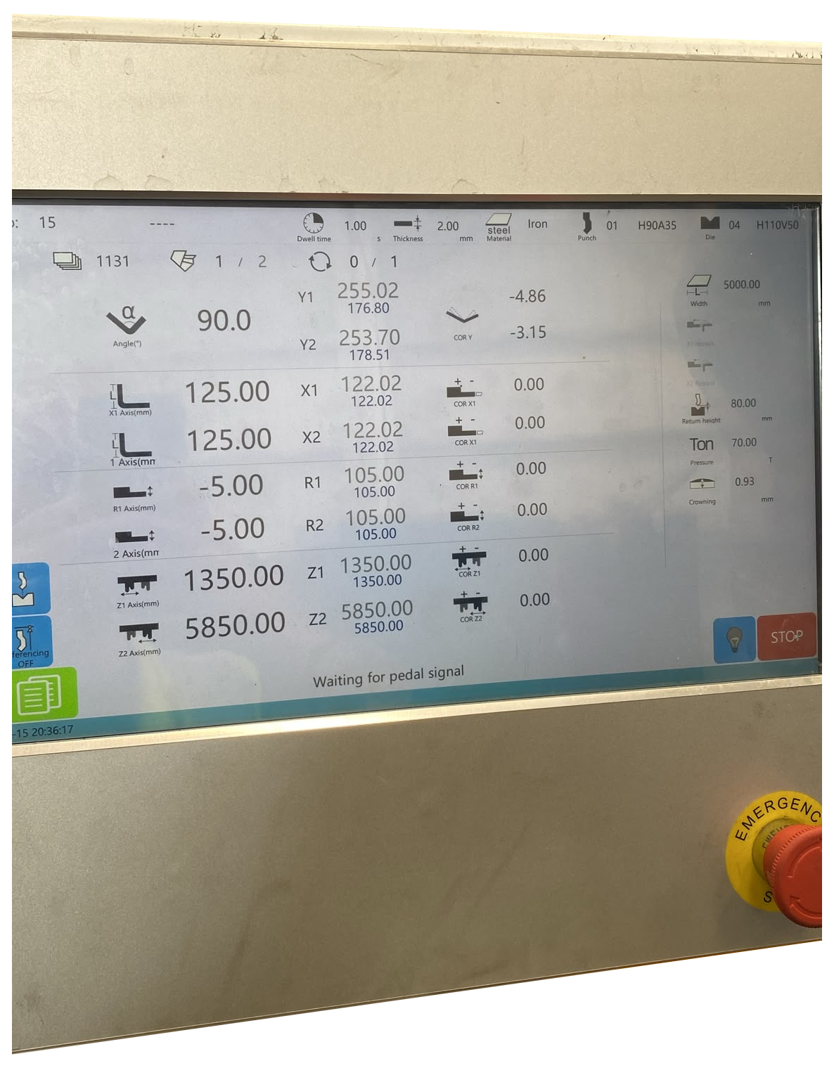
Y1, Y2, X1, X2, R1, R2, Z1, Z2, P and ADS. The operating screen shows the individual axis positions, with bending pressure and crowning on the right.
Left and right ram position for bend-angle and parallelism control.
Each stop finger moves independently towards or away from the tooling.
Independent vertical positioning of the two stop fingers.
Independent powered positioning across the machine width.
The bending force setting, labelled Pressure on the operating screen.
Anti-deflection compensation, labelled Crowning on the operating screen.
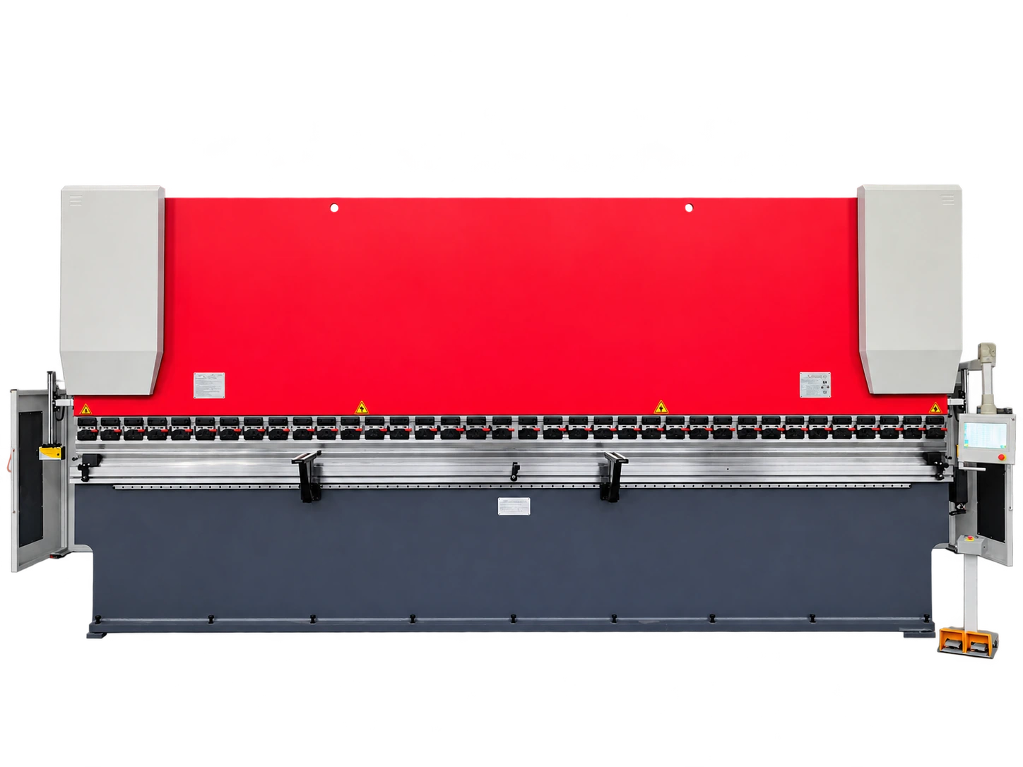
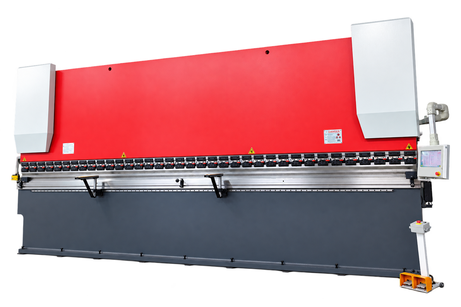
The 7300 mm machine shown here has two independent backgauge fingers, each with powered depth, height and sideways positioning. Other lengths and capacities are available to quote.

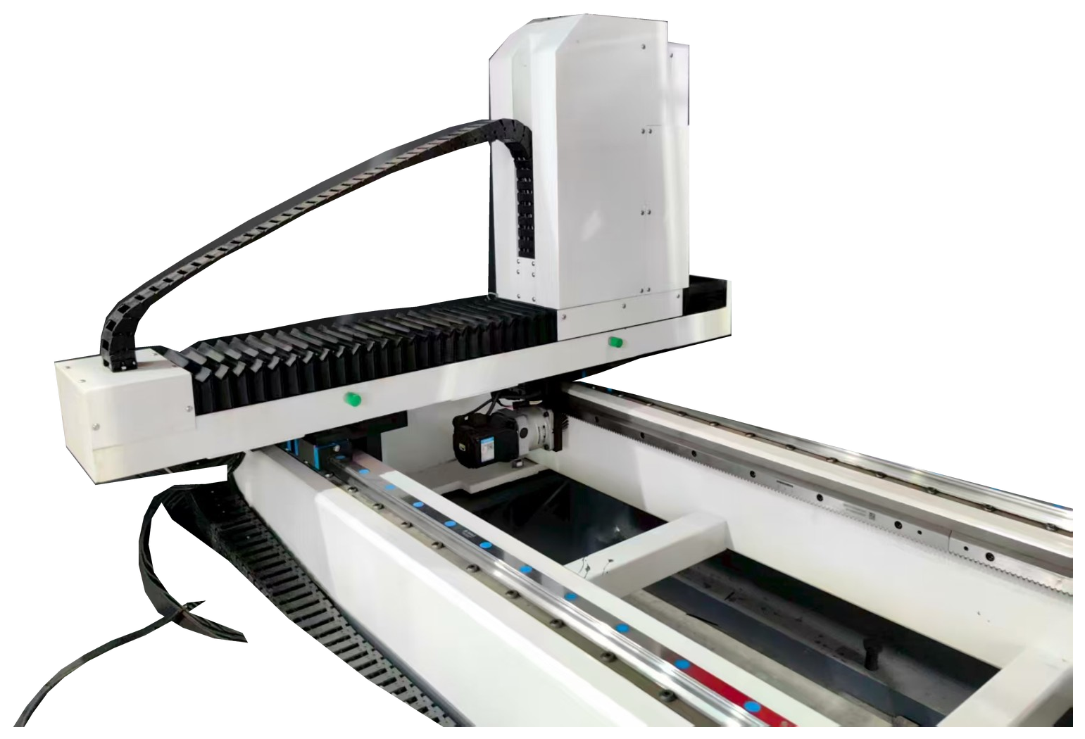
Pay in full or choose a 30% deposit with order. Any balance is due before delivery or collection. Terms and conditions apply.
Prices exclude VAT and delivery. Commissioning and basic training included.
Actual controller photographs


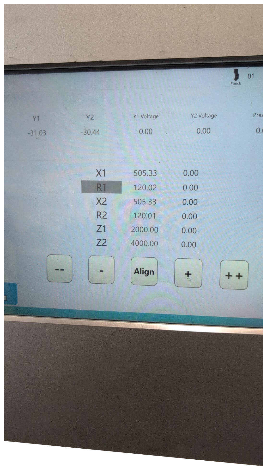
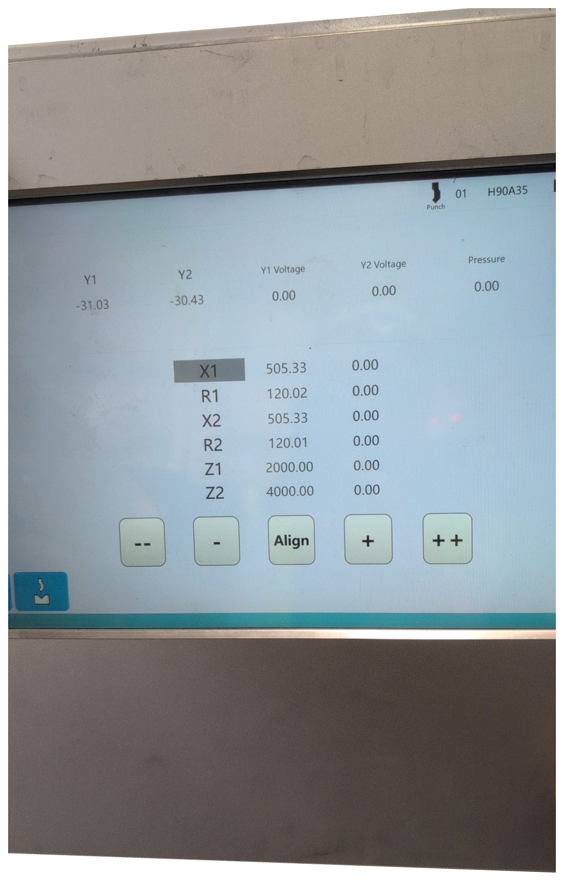
Watch the machine in operation and explore how the two backgauge fingers move independently.
X1/X2, Z1/Z2 and R1/R2 backgauge axes moving at speed, with custom probes made for a client’s specific application.
Open video full sizeThe original 31-second machine video, displayed the right way up.
Open video full sizeZ1/Z2 sideways positioning, X1/X2 depth, and R1/R2 height. A 12-second illustrative sequence; movement speed and travel are not machine specifications.
Open animation full size| Configuration | 10-axis CNC: Y1/Y2, X1/X2, R1/R2, Z1/Z2, P and ADS |
|---|---|
| Backgauge | Two independent fingers with powered depth, height and sideways positioning |
| Controller | Graphical touchscreen with individual axis settings, pressure and crowning control |
| Capacity | 7300 mm machine illustrated; bending length, tonnage and open height specified in the quotation |
| Tooling | Tool holders and punch/die package specified for the required work |
| Price | View models and prices — the illustrated 7300 mm machine, options, delivery and positioning are quoted individually. |
Workshop video
A 58-second guide to tooling, clearance, bend sequence, hole spacing and first-part inspection.
Watch with sound or follow the on-screen captions. Video in English.
Read the bending guideCarter Bend Studio
Follow a bend sequence, see the axis movements and explore tools for your component.
Tell us the bending length, material, thickness and parts you need to make.
Lifetime technical support
Lifetime technical support for machinery supplied by Carter. Telephone and email advice continues after the warranty ends.
All new machines include a 24-month parts-and-labour warranty. Ask about part exchange, finance, delivery, offloading and positioning when requesting your quotation.
Finance is subject to approval. Delivery, handling and positioning are quoted for your machine and site.
CARTER WORKSHOP GUIDE
See how inside radius, K-factor and bend deduction affect the finished part.
These silent animations use a worked example, not a universal deduction table. Different angles, radii, materials, tooling and hems require their own validated allowances. Confirm the dimension convention on the drawing and prove the flat length on a test piece.
A series of closely spaced, shallow bends approximates a larger radius. Also called step bending or facet bending, this process can produce curved panels, covers and transitions.
Small facets and tool marks may remain. Closer spacing can improve the approximation, but tooling and sheet support limit the usable pitch.
Suitable standard punches and dies can often be used. Tight radii, short steps or restricted access may need a different tool arrangement.
This depends on the radius, total change in direction and acceptable faceting. More strokes increase cycle time; there is no universal bend count.
Springback, material variation, tool alignment, stroke depth and feed spacing all influence the result. Axis repeatability is not a guarantee of finished-radius accuracy.
Suitability depends on the selected model, controller functions, tooling, capacity and part clearance. Ask Carter to check your drawing; automatic radius programming is not assumed.
Rolls may suit long continuous curves and cylindrical work. Bump bending can suit parts that also need straight folds; compare finish, geometry and production volume.
For hydraulic models only. Confirm your machine model and existing filter reference before ordering.
Use the manual for the exact model and fitted equipment. These guides support training and job planning; they do not authorise a setup or replace a site-specific risk assessment.
Behind the build
See the frames and beams for CARTER press brakes during production, from heavy steel structures to machining of the working faces.
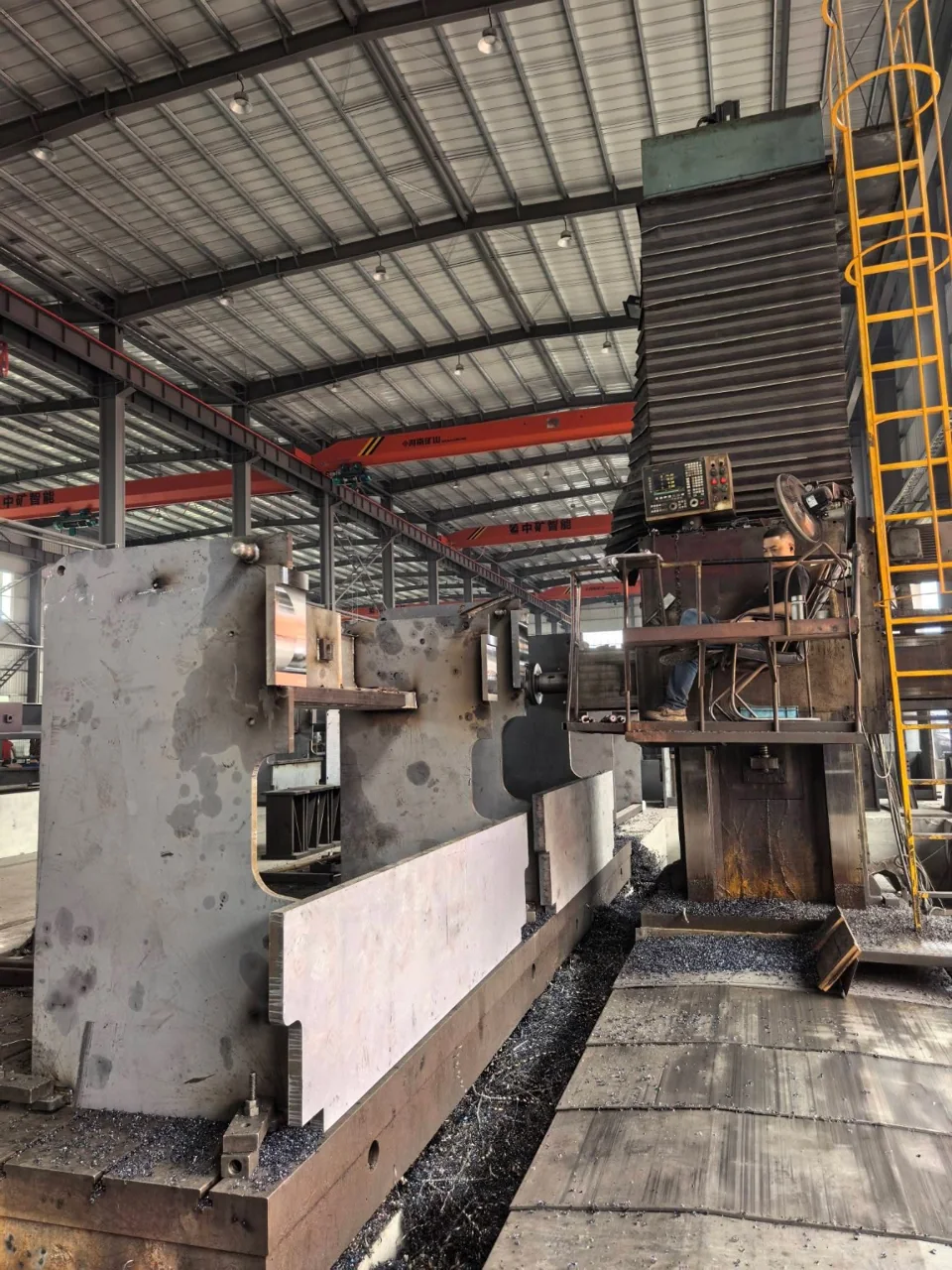
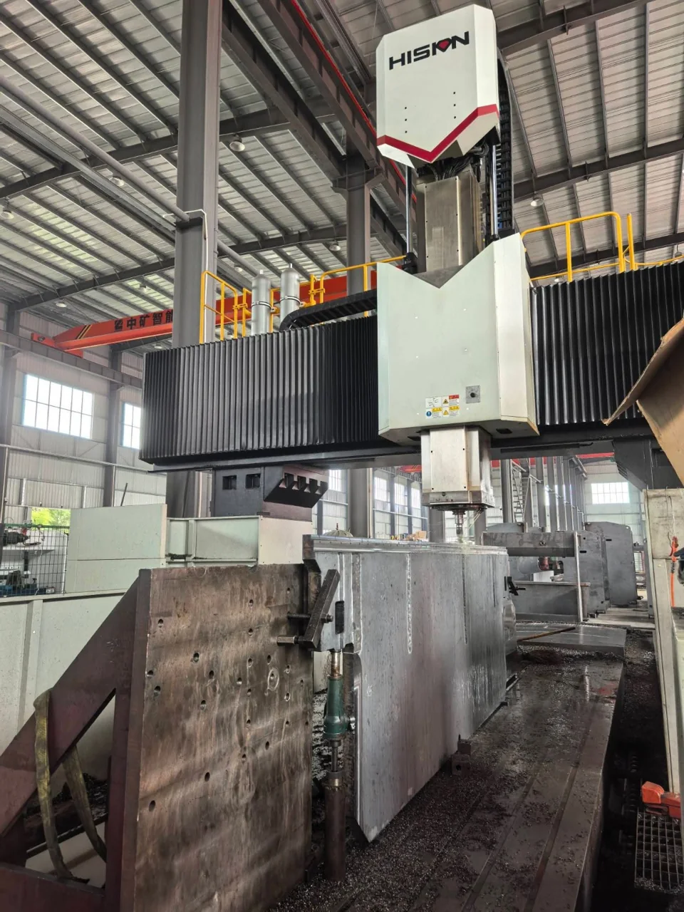
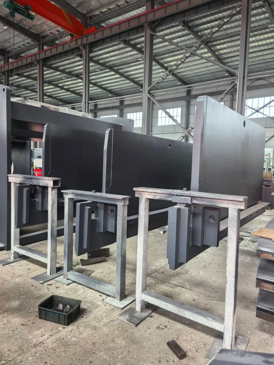
Production photographs from the CARTER press brake range. Frame design and construction vary by model.
Discuss your press brake requirements