
Virtual press brake
Programme it. Position the sheet. Try a bend.
Lengths are along the flat blank between bend centres. Inside angles can be edited below.
Tap corners or drag each segment. Snaps to 45°; adjust exact sizes below afterwards. Grid: 20 mm.
Choose an axis and jog the virtual machine. Y starts at 0 when open; R starts at the die shoulder.
Manual mode demonstrates axis movement. Gauge contact and reach are illustrative.
125 t capacity and 120 mm beam width are demo values. Enter your machine’s figures. The region directly above the punch is treated as solid.
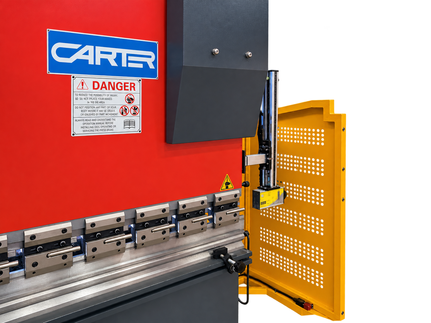
Finger dimensions affect the illustration only. The stepped finger and X/R movement follow the supplied controller screens and backgauge photo.
Fiessler guard alignment
Visual principles only. The exact AKAS model cannot be read from the supplied photo. Setup clearances and test-piece instructions are not confirmed for this machine.
Move both units to the same height to explore optical alignment. The single dashed line is schematic; the actual protective field has multiple beams.
An interrupted protective field stops the closing movement. Optical alignment alone does not verify tool clearance or stopping performance. Real setup and testing must use the matching Fiessler and machine instructions, carried out by trained personnel.
Your machine photograph
Machine view
Ready for first bendAbout this prototype and its calculations
Interface based on the Carter controller photographs showing V2.4.22a. This is a browser training prototype, not the original controller software. Y is relative ram travel, not a calibrated machine coordinate; X/R are schematic gauge positions, not machine settings.
The side-view check samples 21 stroke positions for each bend, retaining earlier bends. It checks the approximated punch and die, entered solid beam width, short flanges and sheet intersections. Punch outlines are scaled to the catalogue height. Curved surfaces and the punch contact region are approximated. Holders, frame throat, gauge collisions, insertion/removal, tool length and springback are not verified. A passing result is a candidate for a setup check, not a guarantee the part can be manufactured.
This first controller demo provides Euram 1010/88° and 1014/88° punches with the standard 2009 four-way die. The bend planner also lets you browse the wider tooling catalogue. Force is an air-bending estimate using the selected material strength. Suggested V starts at 8 × thickness; V below 6 × thickness blocks the demo cycle. Sections use developed bend-centre distances: outside dimensions and bend deductions are not calculated.
Saved programmes stay in this browser. Exported demo files can be reopened here; they are not controller programmes for a real machine.